


In the intricate world of electronics repair, the ability to diagnose and fix issues with precision is paramount. For those who deal with Printed Circuit Boards (PCBs), the stakes are high, and the margin for error is slim.
Traditional methods of PCB repair can be time-consuming and may not always yield the desired results. But what if there was a tool that could revolutionize your repair process? Enter the thermal imaging camera—a game-changer in the field of PCB repair.
Understanding PCB Repair
PCBs are the backbone of electronic devices, hosting a complex network of electronic components. When a PCB fails, it can be due to a variety of reasons such as component malfunction, soldering issues, or even physical damage. Traditional repair methods often involve visual inspection, continuity testing, and sometimes, trial and error.

Introduction to Thermal Imaging Cameras
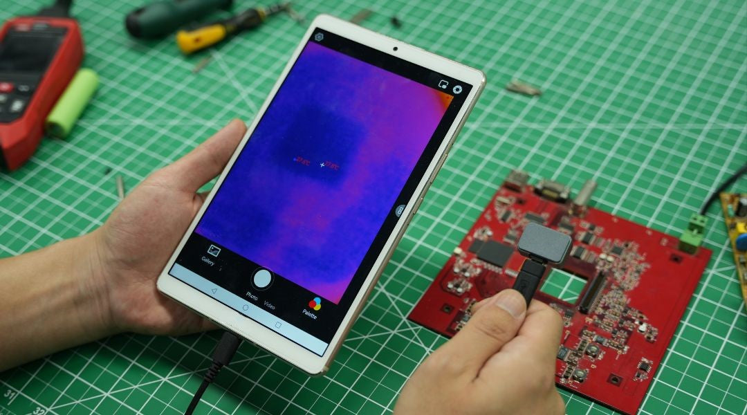
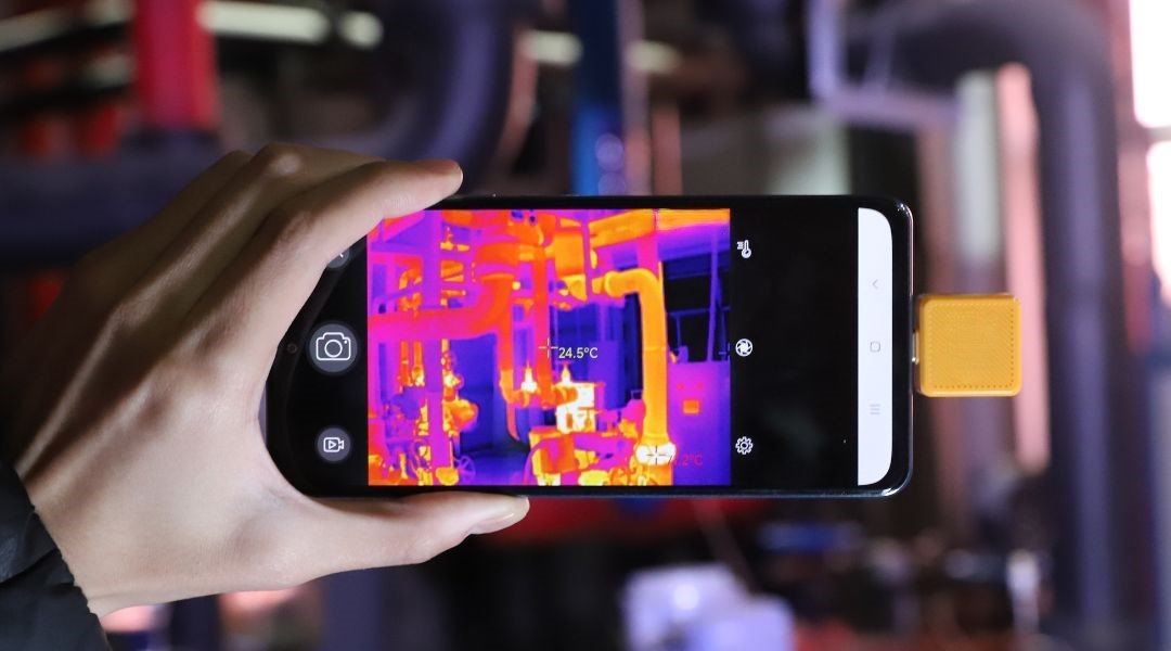
A thermal imaging camera, also known as a thermographic camera, is a device that detects heat. It translates thermal radiation from objects into visible light images through a color palette, allowing users to see variations in temperature. This technology is invaluable in PCB repair, as it can quickly identify hot spots that may indicate a failing component.
The Thermal Master P3 smartphone thermal camera is specifically designed for electronics diagnostics, combining manual focus, high thermal sensitivity, and macro-level inspection capabilities to reveal overheating components and hidden PCB faults.
Benefits of Using Thermal Imaging for PCB Repair
- Improved Accuracy: Thermal imaging cameras provide a visual representation of heat distribution, making it easier to pinpoint the source of a problem.
- Efficiency: Scanning a PCB with a thermal camera is faster than traditional methods, significantly reducing repair times.
- Safety: By identifying potential issues before they become critical, thermal imaging cameras help prevent further damage to the PCB.

Essential Features to Look for in a Thermal Imaging Camera
When choosing a thermal imaging camera for PCB repair, consider the following:
- Resolution: Higher resolution provides more detailed images.
- Temperature Range: Ensure the camera can detect the temperature range typical for PCBs.
- Sensitivity: Look for cameras with the ability to detect small temperature differences.
- Ease of Use: A user-friendly interface is crucial for quick and effective diagnosis.
Step-by-Step Guide to Using a Thermal Imaging Camera for PCB Repair
- Preparation: Clean and stabilize the PCB to ensure accurate readings.
- Setup: Adjust the camera settings according to the PCB's temperature range and sensitivity.
- Scanning: Slowly move the camera across the PCB to capture thermal images.
- Analysis: Examine the thermal images for any unusual heat patterns or hot spots.
- Repair: Once the issue is identified, proceed with the appropriate repair method.

Troubleshooting Common Issues with Thermal Imaging Cameras
- Blurry Images: Ensure the camera lens is clean and the focus is set correctly.
- Interference: Minimize the impact of external heat sources during scanning.
The Future of PCB Repair with Advanced Thermal Imaging Technology
As technology advances, we can expect thermal imaging cameras to become more sophisticated, potentially integrating AI for automated analysis and predictive maintenance. This evolution will further streamline the PCB repair process.
In conclusion, incorporating a thermal imaging camera into your PCB repair toolkit can significantly enhance your diagnostic capabilities and repair outcomes. By leveraging this technology, you're not just improving your skills—you're future-proofing your craft.
Related Reading:
Leave a comment
All comments are moderated before being published.
This site is protected by hCaptcha and the hCaptcha Privacy Policy and Terms of Service apply.