



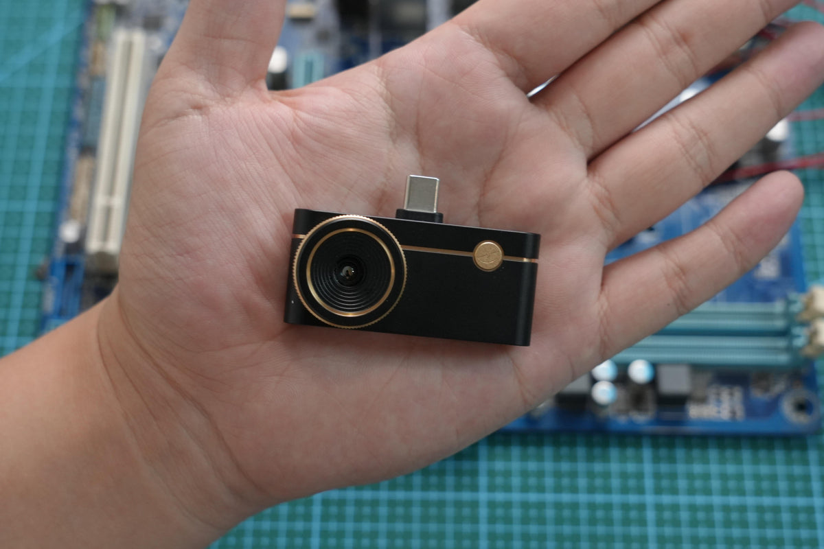
Infrared thermal imaging cameras can help detect abnormal heat generation on PCBs inside robots, giving technicians a chance to spot potential problems before they turn into failures.
The 2026 World Humanoid Robot Games concluded on August 26, with 2,056 robots competing across 51 events. As robot electronics become more complex, abnormal heat from a single component can signal excessive current, a short circuit, or poor heat dissipation.
Which Areas of a Robot PCB Should Be Inspected?
A quick thermal scan can reveal abnormal heat while the robot is running, allowing technicians to focus on high-load and component-dense areas.
Motor Driver Boards
Check MOSFETs, motor driver ICs, and voltage regulators for unusual temperature differences between similar components. Infrared thermal imaging cameras can quickly reveal these hotspots.

Power Management Circuits
Look for localized heat caused by excessive current, component failure, or poor connections. Infrared thermal imaging cameras make these small temperature differences easier to spot.
Control Boards and Other PCBs
Dense component layouts can make overheating difficult to identify visually. Infrared thermal imaging cameras provide a quick way to locate abnormal components and narrow down potential problems.
How to Use Thermal Imaging to Inspect Robot PCBs
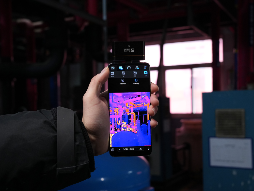
You do not need to inspect every component individually. Start by running the robot under normal operating conditions or a controlled test load. Then scan the control board and other high-load PCBs with a thermal camera such as the Thermal Master P3.

Before scanning, set the appropriate emissivity and working distance for the target surface. Begin with a wider view of the board and look at the overall temperature pattern. Components of the same type should generally have similar thermal behavior under similar operating conditions.
If one component or area stands out, move closer and adjust the focus to get a clearer view. Infrared thermal imaging cameras are useful at this stage because the inspection can move from a broad scan to a close-up check without taking the robot apart or stopping the entire troubleshooting process.
The basic workflow is simple: scan, compare, move closer, and locate.
Practical Applications of Thermal Imaging for Robot PCB Troubleshooting
Once the inspection points are clear, thermal imaging can make PCB troubleshooting more straightforward. Instead of guessing which component may be causing the problem, technicians can first look for unusual heat patterns and then investigate the area in more detail.
Motor Driver Boards
Dane works at a small robotics lab developing quadruped robot prototypes. During one test, one of the robots began behaving differently from the others. After the test, he used the Thermal Master Thor001 to check the motor driver board.

Most of the components were at similar temperatures, but one area showed a small temperature difference.
The Thor001 has thermal sensitivity as low as 35 mK, allowing it to pick up relatively small temperature changes. In this case, the subtle difference gave Dane a useful starting point for further troubleshooting before the issue became more serious.
Power Management Circuits
Power management circuits can be more difficult to inspect because many components are packed closely together. Looking at the board alone does not always make it clear which component is producing the heat. Dane used the Thor001 with a macro lens to take a closer look at the board. The setup made small components and connection points easier to examine, including MOSFETs, ICs, and solder joints. This is especially useful when the suspected hotspot is only a small part of a much larger circuit.
PCB Components
The ideal inspection distance also changes depending on the size of the target. A wider view works better when checking the overall temperature distribution of a board, while a closer view is needed when inspecting individual MOSFETs, ICs, or SMD components.
This is where the P3's adjustable-focus lens becomes useful. A technician can start by scanning the board from a normal working distance, identify an area that looks unusual, and then adjust the focus for a closer inspection. There is no need to keep changing cameras just because the inspection distance changes.
Which Is Better for Robot PCB Inspection?
The right choice depends largely on the type of PCB work you do.

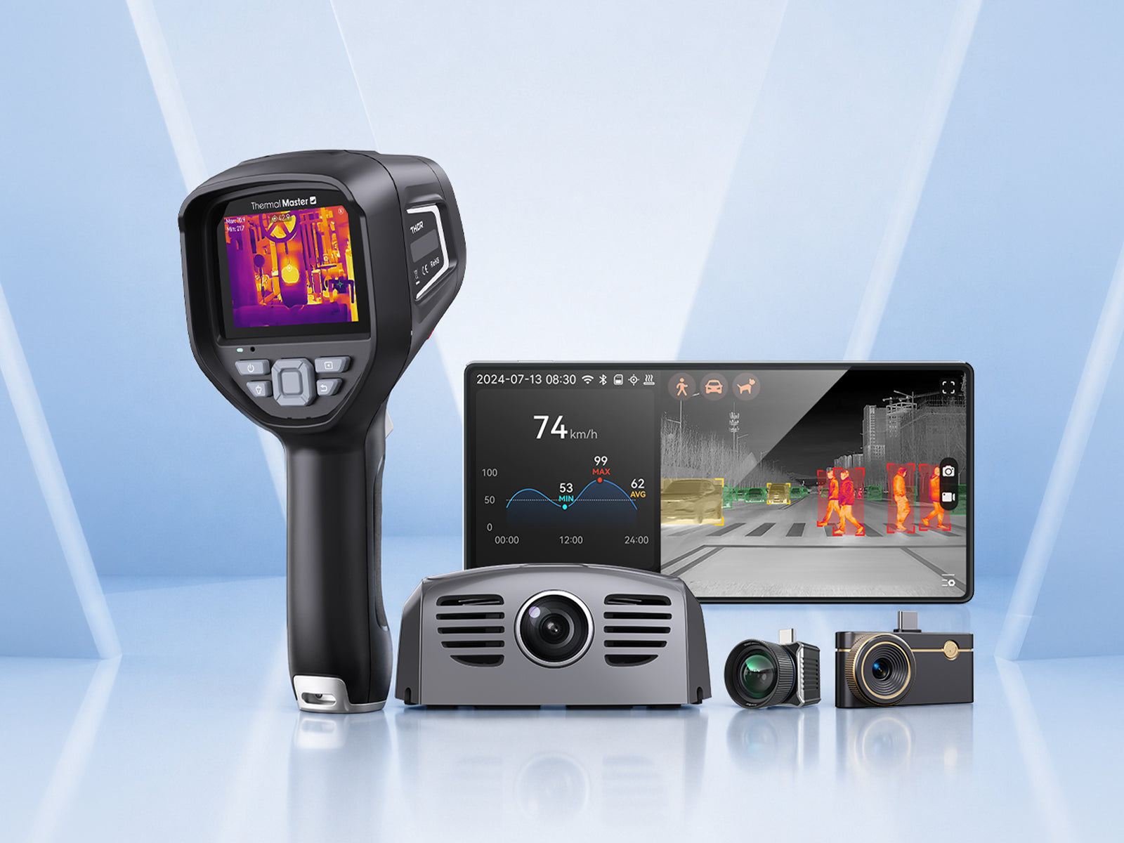
Thor001 works well for close-up inspection, especially when paired with a macro lens. It is a practical option when the main goal is to examine a specific area or small component after a hotspot has already been identified. Thermal Master P3 is more flexible when the inspection involves different working distances. Its adjustable-focus design allows the same camera to be used for a wider PCB scan and then for a closer look at individual components.
For robot PCB inspection, simply scan the board, compare similar components, and investigate any unusual hotspots. Infrared thermal imaging cameras make it easier to spot potential problems before they become costly failures.
Read More
Thermal Cameras for PCB Inspection: 3 Ways to Improve Troubleshooting Efficiency
How to Choose the Right Thermal Camera for Electrical Panel Inspection
Fix or Replace? Thermal Imaging Guides PCB Component Repair

Hinterlasse einen Kommentar
Alle Kommentare werden vor der Veröffentlichung geprüft.
Diese Website ist durch hCaptcha geschützt und es gelten die allgemeinen Geschäftsbedingungen und Datenschutzbestimmungen von hCaptcha.